Balaram Bridge |
 |
Lifting of Superstructure
Three alternative scheme were thought of
- Lifting of superstructure span carried out by lifting of span from top but other
rehabilitation work was in progress, so there was not sufficient space, hence it
was not considered.
- By lifting the span off the articulations, the total vertical load coming 260 T.
it was, how ever not possible to lift the span from the river bed in view of subsoil
water and soil strata is sandy below the span.
- Lifting of span to be carried out from the pier cap with the jack, being convenient,
safe & economical finally this scheme was adopted.
The following method sequence was adopted for lifting of span
 |
|
- Opened the expansion joints and disconnected the spans. The top wearing course including
the bitumen topping was c hipped out to a width of 500 mm along expansion joint.
- All expansion joints were cleared from all debris and dust.
- Provided 12 mm thick epoxy mortar 2:1:20 (Resin: hardener: Silica sand – by weight)
to the diaphragm beams and bearing ends of the girders.
- Drilled 12 mm dia holes to depth of 100 mm at a spacing of 500 mm c/c to the of
diaphragm beams and bearing end regions of the girder and fixed 8 mm dia metal nozzle
in the drilled holes using quick setting grout.
|
- Now carried out Epoxy injection grouting through the nozzles added till rejection
to the bottom half of diaphragm beams and top half of diaphragm beams with polymer
cement grout.
- Polymer Cement grouting was done in the pier cap below the bearings as severe Honey
combing in some of the pier caps was observed.
- Provided steel plate strengthening to the end diaphragm beams by providing. 8 mm
plate on either side of the diaphragm beam and 16 mm plate at the bottom of the
diaphragm beam. The side plates were fixed by drilling through holes in the Diaphragm
beam and fixing by bolts.
- The gap between the steel plate and diaphragm beam was filled up using polymer cement
injection grouting.
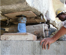
- Now fixed 5 nos. Hydraulic jacks at pier P3 and mechanically jacks were suitably
placed between hydraulic jacks. All the jacks to be placed below the diaphragm beams.
- Set of 3 hydraulic jacks was connected to a single power pack.
- Now the lifting process was commenced by operating all the 5 jacks and simultaneously
tightened the hydraulic jacks. The lifting was done for a minimum height of 60 mm.
same procedure was repeated at P2
Precaution during the lifting of span
- In Diaphragm beam bottom at pier P2 & P3 cracks were observed hence to improve
shear strength and deformation characteristics glass fibre wrapping provided. The
advantages of this wrapping is increase in strength and load carrying capacity without
significant increase in dead load, increased load carrying capacity and better resistance
to seismic forces and deflection, resistance of acids and alkali
- Where jacks were placed, their location/number and size should be selected in such
a manner so that there are no undue stresses developed in the structure.
- All jacks were operated from one control panel by single control lever.
- The jacks were so synchronized that differential lift between individual jacks was
not exceeded 1 mm.
|