Balaram Bridge |
 |
Lifting Operation
Instruments used
 |
|
- Tangee heavy duty hydraulic hand pressure pump maximum pressure 750 kg/cm2.
- Two speed of automatic change over.
- Pressure pipe polynose jack nose 3/8” maximum w.p. 10000 PSI 9690 BAR).
- Hydraulic jacks capacity 75 Tones = 5 No.
- Mechanical jack capacity 50 Tones = 7 No.
- Wooden sleeper and 10 to 25 mm thickness steel plate for packing.
- Hammer 5 Kg weight.
|
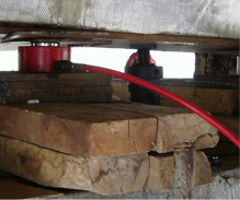
Lifting procedure
- The 5 no. of hydraulic jack’s capacity 75 Tones were used to lift as shown in fig.3. All jacks were operated from one control panel by a single control lever.
- Applied pressure by hand pressure pump on jack and measured height between girder bottom and pier cap top and if required balanced in U/S and D/S by hydraulic jack.
- When span was lifted up to 60 mm in stages. Then load transferred to mechanical jacks (2 no.), wooden sleeper and steel plate were removed from the hydraulic jack.
In view of the magnitude of the lift, it was not possible to do entire lifting in both P2 & P3 one operation and the lifting had to be done in steps. At the end of each lift, it was necessary to lift the hydraulic jacks by inserting packing between the pier cap and hydraulic jack. A very simple screw arrangement was adopted so that hydraulic jack could be lifted manually and the gap filled in the steel plates.
As this was found to be time consuming at site, the method was substituted by use of small hydraulic lifting jack. All the 5 jacks were tested in the hydraulic testing rig for a capacity of 260 Tones prior to commencement of the work. The scheme envisaged a common hydraulic circuit for lifting to be carried out at all 5 points simultaneously. A standby pump was incorporated in the circuit so that the lifting could be done by the second pump (max. pressure 750 kg/cm2) without loss of time in case the first pump develops any defect.
It was anticipated that as the superstructure was lifted, the numbers of plates required for Packing of the jack and also the temporary supports would go on increasing. To ensure that uniform movement was obtained on all jacks, height in between pier cap and girder bottom were measured on the upstream and downstream ends and relative lift of upstream and downstream face was recorded continuously. During the lifting, it was observed that initially the downstream jack traveled more than the upstream jacks thus correcting the tilt.
It was necessary to remove both the top and bottom plates of the original segmental bearings to enable new bearings to be fixed. After the structure was lifted through sufficient height enabling workers to unscrew the nuts fixing bottom and top plates of existing bearing, the work for removal in such plates was taken up during the periods between of 2 sides. It was observed that in some cases, the nuts could not be unscrewed as the bolt threads were damaged due to the impact. Such bolts were therefore cut by gas cutter. After making a pocket in the concrete surrounding the bolt, the pocket filled with epoxy mortar.
To allow working space for inserting new bearing, it was necessary to lift the superstructure higher than the deck level. At the same time, raising the level beyond the original level was considered risky especially in the view of innumerable cracks in the concrete. It was therefore kept at deck slab level thus giving just sufficient space for insertion of the bearings.
|